Mô tả
Tổng quan
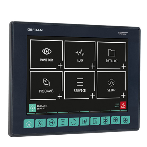
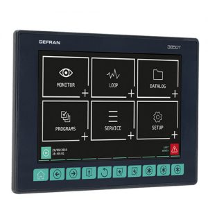
Bộ điều khiển đa năng 3850T là một thiết bị tất cả trong một. Nó kết hợp bộ điều khiển PID chính xác, lập danh mục dữ liệu an toàn, báo cáo hàng loạt, Bộ lập trình điểm đặt (Ramp & Ngâm) và khối chức năng mạnh mẽ sẽ cho phép các chương trình tùy chỉnh với khả năng cấu hình điều khiển trình tự. Giao diện đồ họa cảm ứng 7 ”rực rỡ giúp hiển thị cực kỳ rõ ràng các thông số quy trình. Công nghệ này cũng cung cấp s khả năng, từ phía trước của bộ điều khiển, được cấu hình mà không cần máy tính được kết nối. 3850T đáp ứng các tiêu chuẩn độ chính xác cao của Công nghiệp Hàng không Vũ trụ và Ô tô với CQI9 và AMS2750.
Vòng điều khiển PID
3850T có thể điều khiển tối đa 16 vòng PID riêng lẻ. Tính linh hoạt của 3850T cho phép người dùng sử dụng nhiều chức năng vòng điều khiển nâng cao. Các loại này bao gồm vòng lặp đơn, van tỷ lệ hoặc van cơ giới, điều khiển tỷ lệ và điều khiển tầng.
3850T có nhiều phương pháp điều chỉnh để cho phép người dùng kiểm soát chính xác quá trình. Điều này sẽ đảm bảo kiểm soát nhiệt độ ổn định và chính xác cho các ứng dụng có nhu cầu nhiệt quan trọng hoặc các quy trình nhanh.
Trình ghi dữ liệu và báo cáo hàng loạt
Chức năng Data Logger, kết hợp với Đồng hồ thời gian thực lưu trữ dữ liệu quá trình, tín hiệu IN / OUT và trạng thái cảnh báo trong một tệp đang mở (định dạng .CSV) hoặc tệp được mã hóa. Tần số lấy mẫu dữ liệu tối thiểu là 1 giây. Tùy chọn báo cáo hàng loạt cho phép bạn liên kết dữ liệu đã lưu trữ với một tham chiếu mã hàng loạt cụ thể. Tính linh hoạt của định dạng dữ liệu 3850T sẽ cho phép người dùng tạo các báo cáo tùy chỉnh , sản xuất và chất lượng.
DataLog Utility PC có sẵn để quản lý dễ dàng tất cả dữ liệu đã lưu trữ, cho phép sao chép và xóa tệp theo cách thủ công hoặc tự động qua mạng Ethernet. Dữ liệu được lưu trữ trên PC có thể được hiển thị ở định dạng biểu đồ xu hướng hoặc bảng tính (loại Excel) hoặc xuất dưới dạng tệp CSV hoặc PDF.
Bộ lập trình điểm đặt (Ramp & ngâm)
3850T cung cấp một lập trình viên Set Point tiên tiến cho người dùng để tạo hồ sơ kiểm soát với đoạn đường nối, ngâm, giữ , và sự kiện Trong chức năng / Out cho mỗi bước. Nhiều quá trình có thể được thiết lập để mỗi vùng có thể có thời gian đồng bộ hóa dựa trên thời gian hoặc thời gian không đồng bộ. Các Soaks đảm bảo, nhiều đầu ra sự kiện cho điều khiển phụ có thể được quản lý trong Trình lập trình.
NHẬN logic
GET GEFRAN của luận lý là một lựa chọn al gói lập trình trên bộ điều khiển 3850T. GET logic là một phần của Công cụ GF_Express có sẵn để tải xuống từ trang web của Gefran. GET logic kết hợp các hàm logic và các hàm toán học cho phép người dùng tạo điều khiển trình tự tùy chỉnh với việc sử dụng kết hợp các chức năng điều khiển quy trình nâng cao.
3850T như một thiết bị tất cả trong một, kiểm soát quá trình cấp cao bằng toán học và tích hợp các chức năng logic. Giờ đây, có thể tạo ra các kênh điều khiển ảo, với độ trễ, bộ định thời, điều khiển tuần tự, hàm logic, hàm toán học, cùng với điều khiển PID chính xác cho phép người dùng kết hợp tất cả các chức năng nâng cao thành một giải pháp 3850T.
Giao diện tùy chỉnh NHẬN chế độ xem
Chế độ xem GET cũng nằm trong phần mềm GF_Express của Gefran. GET View cho phép người dùng tạo các trang tùy chỉnh đồ họa cụ thể cho ứng dụng. Chế độ xem GET , cho phép người dùng thiết kế một giao diện đồ họa động sẽ đơn giản hóa và làm rõ ràng các tương tác quy trình trên sàn nhà máy. Gefran’s bao gồm một thư viện biểu tượng đồ họa để hỗ trợ việc phát triển các chế độ xem tùy chỉnh. Có các liên kết dễ dàng để liên kết các ký hiệu đồ họa với các biến bộ điều khiển.
GF Express với GET view & GET logic
GF Express là công cụ cấu hình của Gefran cho tất cả các sản phẩm được cấu hình vi xử lý của họ. GET View và GET logic là các phần của công cụ cấu hình để sử dụng với 3850T.
Dịch vụ từ xa & Bảo mật
3850T có sẵn một số cấp độ mật khẩu và bảo mật. Chúng có sẵn cho người dùng để bảo vệ thiết bị khỏi bị truy cập hoặc sử dụng trái phép.
Khi cần thiết hoặc mong muốn, 3850T sẽ hỗ trợ dịch vụ máy chủ VNC từ xa có thể hoạt động trên PC, Máy tính bảng hoặc Điện thoại Thông minh. Điều này sẽ cho phép xem và chỉnh sửa từ các vị trí địa phương hoặc từ xa. Các cấp độ bảo mật cho truy cập cục bộ cũng áp dụng cho truy cập từ xa. Dịch vụ từ xa có thể được sử dụng để chẩn đoán và xem quy trình nhằm hỗ trợ tăng thời gian sản xuất và khắc phục sự cố thiết bị.
Thông số kỹ thuật của 3850T
| OPERATOR INTERFACE | ||
|
DISPLAY | Type | TFT Touch Screen with 4-wire resistive type technology |
| View area | Diagonal: 7” Dimensions (L × H): 152 × 90 mm (5.98” x 3.54”) | |
| Lighting | Back lit with LED, duration 50.000 hours @ 25 °C (77 °F) | |
| Resolution (pixel) | 800 × 480 (WVGA) | |
| Colors | 262,000 | |
| Max brightness | 240 cd/m2 | |
| Contrast | 1000:1 | |
| View angle | Horizontal: 60° Vertical: +45° … -60° | |
| KEYBOARD | Number of keys: 10 (of which 3 programmable) Type: mechanical | |
| CONTROL FUNCTIONS | ||
|
LOOP (Regulation) | Type | Single loop; Cascade (2 consecutive PID: PID1-PID2, PID3-PID4 …); Ratio; Valve |
| PID | Number: 16 max Parameter groups: 10 max | |
| Regulation type | PID ON/OFF Single action heat or cool Double action heat or cool | |
| Control output | Type: continuous (0… 100%) or ON/OFF with PWM modulation. Cycle time: constant or optimised (Burst Firing) | |
| Valve control | Open/close for floating type motorized valve Open/close for motorized valve with feedback (potentiometer position control) | |
| Sampling time | 25 ms | |
| Tuning | Automatic Self Tuning algorithms. | |
| Alarms | Number: max 4 associated with each PID Type: maximum, minimum, symmetric, absolute/relative | |
|
SETPOINT PROGRAMMER | Programmer type | Synchronous and asynchronous setpoint programs Single-segment setpoint or ramp + maintenance profile Integrated function blocks |
| Program profile | From 1 to 4 synchronous profiles | |
| Program | Max number of programs: 250 Maximum number of programs running at the same time: 8 Available commands: START, HOLD/PAUSE, RESET, END, SKIP Status outputs: RUN, READY,END, HOLD | |
|
Segments | Setting: time segments (dd:hh / hh:mm / mm:ss) or gradient con- figuration Maximum number of segments per program: 50 Maximum number of ramps and holds per program: 100 (50 ram- ps – 50 holds) High/low limit threshold configurable for each segment PID group activation for each segment | |
| IN profile events | Max number of settable IN events: 16 Acknowledged events: digital IN-resource, digital OUT, system merker | |
| OUT profile events | Max number of settable OUT events: 16 ON/OFF while running the profile segment Events acknowledged: digital OUT resource, logic operation, programmer status | |
| Simplified configurability | Template Configuring and running the same program on several PIDs simul- taneously | |
| HBB alarm | Alarm range configuration per single segment High/low range setpoint | |
|
GETLogic | Scope | Sequential execution of logical and mathematical instructions |
| Running sequences | 1 for each program (max 8) + 1 global always active | |
| Function blocks | Max number per program: 400 | |
| Logic function blocks | AND, OR with default logic patterns Set/Reset, Reset/Set Rising edge, trailing edge | |
| Timer function blocks | Excitation delay timer (TON) De-energising delay timer (TOFF) Flip/flop timer | |
| Counter function blocks | Increasing counter Decreasing counter | |
| Basic mathematical function blocks | + , – , × , : , average, minimum value, maximum value, square root, base 10 logarithm, natural base A logarithm, and raised to the power A, A raised to the power B | |
| Special mathematical function blocks | Max peak, minimum peak, hold of a value, average of 2 values, minimum/maximum limit of a value | |
| Special mathematical function blocks | Selection between two values Greater/Lesser/Equal/Greater- Equal/Lesser-Equal/Different | |
| Process function blocks | F0 (sterilisation coefficient) | |
| Resources for mathematics operators | Analog IN/OUT, SP controller, System Log/Real data | |
| Resources for logical operators | Digital In/Out, Alarm Status, System Merker | |
|
DATA LOGGER | Scope | Continuous configured data recording |
| Recordable values | Max number of analog values: 50 Max number of digital events: 50 | |
|
Sampling | Sampling interval: 1 s … 1 h Sampling mode: single record with time information (date/time) and values/events/actions detected Closing the sequential log file: automatic every hour/day/week (configurable) | |
|
Data storage | File format: CSV Data file encryption: optional Log file name with close date/time indication Storage media: internal memory File export: manual via USB key or manual/automatic via Ethernet via Gefran – DataLog Utility PC application – Report Utility | |
|
Graphic display | Graph: stored log data trend Max number of viewable curves: 8 Data selection by association: 8 curves Single curve scaling Available functions: enable single curve, full scale selection, zoom +/-, scroll +/- and cursor | |
|
PRODUCTION REPORT (Batch report) | Scope | Synchronous recording when running the program profile |
| Recordable values | Max number of analog values: 50 Max number of digital events: 50 Batch name/description (selectable) Running profile data (selectable) | |
| Sampling | Sampling interval: 1 s … 1 h Sampling mode: single record with time information (date/time) and values/events/actions detected | |
|
Data storage | File format: CSV Data file encryption: optional Log file name with close date/time indication and Job ID reference (optional) Storage media: internal memory File export: manual via USB key or manual/automatic via Ethernet via Gefran – DataLog Utility PC application – Report Utility | |
|
Graphic display | Graph: stored log data trend Max number of viewable curves: 8 Data selection by page: 8 curves Single curve scaling Available functions: enable single curve, full scale selection, zoom +/-, scroll +/- and cursor |
|
TREND GRAPH REAL TIME | Scope | Continuous recording of data configured without archiving |
| Recordable values | Max number of analog and digital values: 24 | |
|
Graphic display | Max number of viewable curves by page: 24 Number of samples: 5,000 Single curve scaling Available functions: enable single curve, full scale selection, zoom +/-, scroll +/- and cursor | |
|
PROGRAM RECIPE | Data file | Programmer profile segment/event configuration Synchronised programmer logic operations Synchronised programmer mathematics functions DataLog/Batch data configuration |
| References | Descriptive name and ID code (easy loading and activation) | |
| Data import and export | Via USB key | |
|
CONFIGURATION RECIPE |
Types | System: number of clocks, home page, program modes … PID: all single PID configuration parameters GETView: custom page configuration InOut: analog channel range, decimal point configuration, unit of measure configuration Messages: custom text list |
| Data import and export | Via USB key | |
|
GETView | Scope | Configure custom graphic pages directly from the controller panel |
| Number of customisable pages | 10 max | |
|
Components | Available types: • Led: digital variable with color/text/image change • Notes: default text display • Text: fixed text display • Edit text: text view and edit • Progress: display a value as a bar (vertical/horizontal) • Data display: display of a numeric value • Data edit: view and edit a numeric value • Button: change the status of a digital value with status di- splay (color/text/image) and change mode selection (momen- tary/toggle) • System: page change function with default list selection Maximum number of components of the same type per page: • Text (Note, Text, Edit text) and numerical (Display date, Edit date): max 40 • Key: max 20 • LED: max 20 • Progress: max 16 • Image: max 10 • System: max one link of each type | |
|
Available functions | Add a new component Edit component parameters Delete a component Move a component Multiple component selection for move or delete Align multiple components left Align multiple components top | |
| Image functions | Image conversion tool from the most popular graphic file formats Image file import and export via USB key | |
|
WEEKLY CLOCK | Scope | Event (ON/OFF) on a weekly or daily basis |
| Function | Configure ON/OFF event status by single day of the week Event time settings in hh:mm Enable the weekly clock Enable weekly repetition | |
| Number | 4 max |
|
MULTILINGUAL | Scope | Change message language |
| Function | UNICODE support Custom message translation File import and export via USB key | |
| Available languages | Italian (ITA), English (ENG), French (FR) | |
|
DIAGNOSTICS | Scope | Controller operating status |
| PID loop | Short circuit or probe opening Interrupted or partially interrupted load (HB alarm) | |
| Communication | Communication status between panel and I/O modules Communication error alarm | |
| I/O modules | Signal status and single channel values | |
| System | Disk Full Alarm | |
| ALARMS | Number | 254 max |
| Function | Alarm message customisation ACK/no ACK selection Real alarm display priority order level settings | |
|
VARIABLES |
Available types | Merker (boolean) Retain Merker (boolean) Register (32 bit with sign) Retain Register (32 bit with sign) Real (32 bit) Retain Real (32 bit) String (text message) Function |
| Number | max 256 per type | |
|
USERS | Levels | Number of default levels: 3 (operator, level 0; Maintenance, level 1; OEM manufacturer, level 2) |
| Safety | Password Automatic timed logout at operator level | |
| Internal functions | Add new user | |
| REMOTE CONNECTIVITY | Modbus TCP | Modbus TCP Slave HMI/SCADA/DCS Data exchange systems |
| VNC | Remote page standard interface Remote machine maintenance | |
|
REPORT UTILITY (external tool) | Connection | Ethernet Server NTP (option) |
|
Function | Remote DataLog and batch management Encrypted DataLog and batch file decryption Manual controller file copy or deletion Timer Configuration for automatic controller file copy or deletion Data trend graphic display (with graph zoom and scroll) Data display in spreadsheet mode Data export in .CSV or .PDF format | |
|
GF_eXpress (PC configuration) | Connection | Ethernet |
|
Function | PID controller configuration read and write Graphic display and setting of parameters useful for Programmer functions Logic and mathematics operation settings and display Creating custom graphic pages | |
|
NON-VOLATILE MEMORY | Type | FRAM |
| Capacity | 32 kB retentive variables | |
| Write | Max number: > 1012 cycles Retention: > 10 years @ 55 °C (131 °F), > 55 years @ 35 °C (95 °F) |
| GENERAL DATA | ||
|
VOLTAGE | Operating voltage | 24 VDC ±25% |
| Current absorption | 300 mA max | |
| Dissipated power | 8.5 W max | |
| Protections | For polarity exchange For short circuit | |
| Connection | Removable 3-pin polarised connector Screw terminals, max 2,5 mm2 (0.0038 in2 ) (13 AWG) cable sec- tion | |
|
BUFFER BATTERY | Type | Ml2032, not replaceable |
| Specifications | Rechargeable Li-Al, 3 V 65 mAh | |
| Duration | 10 years. High temperatures can reduce battery life. | |
| Power reserve in the absence of current | > 20 months | |
| Ethernet (ETH) | Connector: RJ45 Speed: 10 / 100 Mbit/s Signals: Green LED = connection, yellow LED = data transfer Protocols: FTP (File Transfer Protocol), Modbus TCP/IP Slave | |
|
USB | Connector: type A Type: Host Port Version: 2.0 Full Speed Current: 100 mA max File system for USB key (Flash Drive): FAT32 | |
| ENVIRONMENTAL CONDI- TIONS | Indoor | Use |
| Operating temperature | 0 … +50 °C (32… 122 °F) (according to IEC 68-2-14) | |
| Storage temperature | -20 … +70 °C (-4…… 158 °F) (according to IEC 68-2-14) | |
| Relative humidity | Max 95% RH non condensing (according to IEC 68-2-3) | |
| PROTECTION RATING | IP 65 on the front (according to IEC 68-2-3) | |
| ASSEMBLY | Positioning | On panel, front pull-out |
| Installation requirements | Installation category: II Pollution rating: 2 Insulation: double | |
| DIMENSIONS | (L × H × D) | 198 × 134.4 × 65,8 mm (7.79” x 5.29” x 6.63”) max |
| WEIGHT | 0.5 kg (1.10 lb) | |
|
EC REGULATIONS | EMC conformity (electromagnetic compatibility) | Compliance with the 2014/30/EU Directive EMC Emission: EN 61000-6-4 EMC Immunity: EN 61131-2, EN 61000-4-2, EN 61000-4-3, EN 61000-4-4, EN 61000-4-5, EN 61000-4-6, EN 61000-4-8, EN 61000-4-11 |
| LV conformity (Low Voltage) | Compliance with Directive 2014/35/EU LVD safety: EN 61010-1 | |
| UL REGULATIONS | Compliance with UL508 standard | |
F-GCANs communications module
| GENERAL DATA | ||
|
VOLTAGE | Operating voltage | 24 VDC ±25% |
| Current absorption | 2 A max | |
| Dissipated power | 2.5 W | |
| Connection | Polarised connector with spring terminals, cable 1 mm2 (0.0015 in2) (17 AWG) max | |
| CONNECTIONS | CAN | Connector: DB9 Protocol: CANopen 2.0B, level CAN DS301 v.3.0, v4.0 |
| SIGNAL ELEMENTS | Error | Red LED |
| Running | Green LED | |
| Voltage | Yellow LED | |
| ENVIRONMENTAL CONDI- TIONS | Indoor | Use |
| Operating temperature | 0 … +55 °C (32…. 131 °F) | |
| Storage temperature | -20 … +70 °C (-4…… 158 °F) | |
| Relative humidity | max 95% RH non-condensing | |
| PROTECTION RATING | IP20 | |
| ASSEMBLY | Positioning | Vertical |
| Mount | On DIN 35 mm (1.38”) rail | |
| DIMENSIONS | (L × H × D) | 25.4 × 92 × 90 mm (1” x 3.62” x 3.54”) |
| WEIGHT | 0.15 kg (0.33 lb) | |
|
EC REGULATIONS | EMC conformity (electromagnetic compatibility) | Compliance with the 2014/30/EU Directive EMC Emission: EN 61000-6-4 EMC Immunity: EN 61131-2, EN 61000-4-2, EN 61000-4-3, EN 61000-4-4, EN 61000-4-5, EN 61000-4-6, EN 61000-4-8, EN 61000-4-11 |
| UL REGULATIONS | Compliance with UL508 standard | |
F-MIX module
| INPUTS | ||||||
| Number | 4 configurable + 2 by amperometric transformer | |||||
| Sensor type | TC, RTD (PT100, PT1000), IR sensor, linear DC | |||||
| Single-ended voltage input | Voltage: 0…10 V, 0…2,5 V | |||||
| Impedance: >5 MΩ (channel 1: > 50 MΩ) | ||||||
| Differential voltage input | Voltage: 0…60 mV | |||||
| Impedance: >5 MΩ | ||||||
| Current input | Current: 0…20 mA, 4…20 mA | |||||
| Load: 100 Ω | ||||||
| Potentiometer input | Potentiometer resistance: 100 Ω min. | |||||
| Impedance: >5 MΩ (channel 1: > 50 MΩ) | ||||||
| Extensometer input | Voltage: -5…35 mV, -10…130 mV | |||||
| Impedance: > 5 MΩ | ||||||
| TC input | Thermocouple: J, K, R, S, T, N, C, D, E, B, L (CJ internal) | |||||
| (thermocouple) | Impedance: > 5 MΩ | |||||
| RTD input | Number of wires) 2, 3 or 4 | |||||
| (thermoresistance) | Thermoresistance: PT100, PT1000 | |||||
| rms current: 0…50 mA RMS | ||||||
| Input from a current transformer | Frequency: 50/60 Hz | |||||
| Impedance: 50 Ω | ||||||
| Temperature unit of measure | ° C or ° F, selectable | |||||
| Probe voltage | Voltage: stabilized 10 VDC or 1 VDC, selectable | |||||
| Current: 130 mA max | ||||||
| Resolution | 16 bit | |||||
| Input type | Number | Min | Max | Resolution | ||
| Voltage 0…10 V | Number | 0 | 65535 | 0,15 mV | ||
| Voltage 0…2,5 V | Number | 0 | 65535 | 0,04 mV | ||
| Voltage 0…60 mV | Number | 0 | 65535 | 0,9 μV | ||
| Current 0…20 mA | Number | 0 | 65535 | 0,3 μA | ||
| Current 4…20 mA | Number | 13107 | 65535 | 0,3 μA | ||
| Potentiometer | Number | 0 | 65535 | |||
| ANALOG | Extensometer -5…35 mV | Number | 0 | 65535 | 0,6 μV | |
| Extensometer | Number | 0 | 65535 | 2,14 μV | ||
| -10…130 mV | ||||||
| J thermocouple | °C | -210,0 | 1200,0 | 0,1 °C | ||
| °F | -346 | 2192 | 0,2 °F | |||
| K thermocouple | °C | -270,0 | 1372,0 | 0,1 °C | ||
| °F | -454 | 2501 | 0,2 °F | |||
| R thermocouple | °C | -50,0 | 1768,0 | 0,1 °C | ||
| °F | 32 | 3182 | 0,2 °F | |||
| S thermocouple | °C | -50,0 | 1768,0 | 0,1 °C | ||
| Format and resolution | °F | -58 | 3214 | 0,2 °F | ||
| T thermocouple | °C | -270,0 | 400,0 | 0,1 °C | ||
| °F | -454 | 752 | 0,2 °F | |||
| N thermocouple | °C | -270,0 | 1300,0 | 0,1 °C | ||
| °F | -454 | 2372 | 0,2 °F | |||
| C thermocouple | °C | 0,0 | 2300,0 | 0,1 °C | ||
| °F | 32 | 4172 | 0,2 °F | |||
| D thermocouple | °C | 0,0 | 2300,0 | 0,1 °C | ||
| °F | 32 | 4523 | 0,2 °F | |||
| E thermocouple | °C | -270,0 | 1000,0 | 0,1 °C | ||
| °F | -454 | 1832 | 0,2 °F | |||
| B thermocouple | °C | 44,0 | 1800,0 | 0,1 °C | ||
| °F | 32 | 3272 | 0,2 °F | |||
| L thermocouple | °C | -200,0 | 900,0 | 0,1 °C | ||
| °F | -328 | 1652 | 0,2 °F | |||
| RTD PT100 | °C | -200,0 | 850,0 | 0,1 °C | ||
| °F | -328 | 1562 | 0,2 °F | |||
| RTD PT1000 | °C | -200,0 | 850,0 | 0,1 °C | ||
| °F | -328 | 1562 | 0,2 °F | |||
| TA | mA | 0,0 | 50,0 | 0,01 mA | ||
|
ANALOG |
Accuracy | TC input (*) Note 1 Calibration: < ±(0,25% of value read in °C + 0,1 °C / 0,2 °F) Linearisation 1,8 % of value read Cold joint: < ±1 °C (34,7 °F) at 25 °C (77 °F) room temperature Cold joint compensation > 30:1 rejection at room temperature change
RTD input Calibration: < ±(0.15% of value read + 0.4 °C / 0,72 °F) Linearisation: 0.1% of value read Thermal shift: < ±(0.005% of the value read in °C + 0.015°C / 0,072 °F) /°C starting from 25 °C (77 °F) room temperature Linear inputs: Calibration: < 0.1% full scale Thermal shift: < ±0.005% full scale /°C starting from 25 °C (77 °F) room temperature
CT input Calibration : <0,5% full scale Thermal shift : <+/- 0,01% full scale/°C starting from 25°C (77 °F) | ||||
| Conversion time | 5 ms | |||||
| Protection | Polarity inversion Power surge: max 1 kV per 1 ms | |||||
| Electric insulation | Channel-bus: 2.0 kV | |||||
| Diagnostics | Module state: LED and software | |||||
|
DIGITAL | Number | 8 | ||||
| Voltage | Rated: 24 VDC (according to EN 61131-2 type 1 and type 3) Max: 32 V, 10 mA | |||||
| Switch limit | Low level: ≤ 8 VDC High level: ≥ 11 VDC | |||||
| Protection | Polarity inversion Power surge: max 1 kV per 1 ms | |||||
| Electric insulation | Channel-bus: 2.0 kV | |||||
| Diagnostics | Module state: LED and software Channel state: LED and software | |||||
| (*) Note 1 : for TC S valid with T>100°C; for TC B valid with T>200°C | ||||||
| ANALOG | ||||||
|
OUTPUTS | Number | 2 | ||||
| Voltage output single-ended | ±10 V, 15 mA max | |||||
| Current output | 0…20 mA, 4…20 mA Max load: 600 Ω | |||||
| Resolution | 16 bit | |||||
| Format and resolution | Output type | Number | Min | Max | Resolution | |
| ±10 V | Number | -32768 | 32767 | 0.3 mV | ||
| 0…20 mA | Number | 0 | 32767 | 0.6 μA | ||
| 4…20 mA | Number | 6550 | 32767 | 0.6 μA | ||
| Accuracy | Calibration precision: ±0,1% full scale @ 25 °C (77 °F) | |||||
| Conversion time | 5 ms | |||||
| Adjustment time | 100 μs | |||||
| Protection | Short circuit: ±10 V Overload ±10 V: 16 mA max per each channel Open circuit 0…20 mA / 4…20 mA: Alarm status for open circuit Power surge: max 1 kV per 1 ms | |||||
| Electric insulation | Channel-channel: No Channel-bus: 2.0 kV | |||||
| Diagnostics | Module state: LED and software Channel state: LED and software | |||||
|
DIGITAL | Number | 8 |
| Voltage | 24 VDC ±25% | |
| Current | Single output: 1 A max Total outputs: 4 A max | |
| Groups | 1 group with 8 outputs | |
| Protection | Short circuit Overload per output @ I ≥ 2,2 A for 500 ms min. Over temperature Power surge: max 1 kV per 1 ms | |
| Electric insulation | Channel-bus: 2.0 kV | |
| Diagnostics | Module state: LED and software Channel state: LED and software | |
| GENERAL DATA | ||
| CHANNELS | Number | 24 |
| VOLTAGE | Operating voltage | 24 VDC ±25% |
| Current absorption | 150 mA max | |
| Dissipated power | 7.8 W | |
| CONNECTIONS | Connector | Front 36 pole Wire connection with self-locking spring terminals, max cable sec- tion 0,2…1,5 mm2 (24…15 AWG) |
| ENVIRONMENTAL CONDI- TIONS | Indoor | Use |
| Operating temperature | 0 … +55 °C (32…. 131 °F) | |
| Storage temperature | -20 … +70 °C (-4….. 158 °F) | |
| Relative humidity | max 95% RH non-condensing | |
| PROTECTION RATING | IP20 | |
| ASSEMBLY | Positioning | Vertical |
| Mount | On DIN 35 mm (1.38”) rail | |
| DIMENSIONS | (L × H × D) | 25,4 × 92 × 90 mm (1” x 3.62” x 3.54”) |
| WEIGHT | 0.13 kg (0.29 lb) | |
| CERTIFICATIONS | CE, UL If the appropriate calibration is performed in the field, the Con- troller meets the requirements of standard AMS2750 and may be used in applications requiring the NADCAP directive | |
F-EU16 module
| INPUTS | ||
|
DIGITAL | Number | 8 |
| Voltage | Rated: 24 VDC (according to EN 61131-2 type 1 and type 3) Max: 32 V, 25 mA | |
| Switch limit | Low level: ≤ 8 VDC High level: ≥ 11 VDC | |
| Filter | Hardware: 100 Hz or 5 kHz selectable from software | |
| Protection | Polarity inversion Power surge: max 1 kV per 1 ms | |
| Electric insulation | Channel-bus: 2.0 kV | |
| Diagnostics | Module state: LED and software Channel state: LED and software | |
| ANALOG | ||
|
DIGITAL | Number | 8 |
| Groups | 2 group with 4 outputs | |
| Voltage | 24 VDC ±25% | |
| Current | Single output: 2 A max Single group: 5 A max Total outputs: 8 A max | |
| Protection | Short circuit Overload per output @ I ≥ 2,2 A for 500 ms min. Over temperature Power surge: max 1 kV per 1 ms | |
| Electric insulation | Channel-bus: 2.0 kV | |
| Diagnostics | Module state: LED and software Channel state: LED and software | |
| GENERAL DATA | ||
| CHANNELS | Number | 16 |
| VOLTAGE | Operating voltage | 24 VDC ±25% |
| Current absorption | 8 A max | |
| Dissipated power | 9 W | |
| CONNECTIONS | Connector | Front 26 pole Wire connection with self-locking spring terminals, max cable sec- tion 0,2…1.5 mm2 (24…15 AWG) |
| ENVIRONMENTAL CONDI- TIONS | Indoor | Use |
| Operating temperature | 0 … +55 °C (32…. 131 °F) | |
| Storage temperature | -20 … +70 °C (-4….. 158 °F) | |
| Relative humidity | max 95% RH non-condensing | |
| PROTECTION RATING | IP20 | |
| ASSEMBLY | Positioning | Vertical |
| Mount | On DIN 35 mm (1.38”) rail | |
| DIMENSIONS | (L × H × D) | 25.4 × 92 × 90 mm (1” x 3.62” x 3.54”) |
| WEIGHT | 0.13 kg (0.29 lb) | |
| CERTIFICATIONS | CE, UL | |







Đánh giá
Chưa có đánh giá nào.