Mô tả
Tổng quan
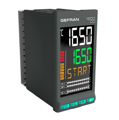
Bộ điều khiển PID và đo lường tiềm năng carbon trong các ứng dụng nhiệt luyện kim loại.
Kết nối trực tiếp của các đầu dò oxit zirconi, thuật toán hiệu quả để tính toán phần trăm carbon bên trong lò kết hợp với điều khiển PID chính xác, cung cấp giải pháp điều khiển an toàn và nhỏ gọn ngay cả cho các ứng dụng quan trọng.
Bộ điều khiển PID vòng lặp đơn / kép
Nhờ đầu vào tương tự thứ ba, ngoài các tín hiệu nhiệt độ và mV cần thiết để quản lý đầu dò zirconia, bộ điều khiển 1650CC có thể điều khiển cả vòng điều khiển Tiềm năng carbon và vòng điều khiển nhiệt độ lò.
Đã nhúng Zirconia vấn đề làm sạch trình tự Burnoff
Đầu dò oxy zirconium là một cảm biến đặc biệt nhạy cảm và do được lắp đặt bên trong lò có bầu khí quyển giàu carbon, sau vài giờ hoạt động, nó cần các trình tự làm sạch theo chu kỳ để loại bỏ sự lắng đọng vật liệu trên phần tử đo, một vấn đề có thể gây ra sai số trong phép đo phần trăm carbon hoặc giảm tuổi thọ trung bình của đầu dò.
Với mục đích này, bộ điều khiển PID tự động quản lý trình tự làm sạch theo thời gian, đồng thời xử lý trạng thái của các giá trị được tính toán, các giá trị này vẫn phải đóng băng trong giai đoạn làm sạch.
Chẩn đoán thăm dò Zirconia
Chẩn đoán thăm dò, hữu ích để xác minh và đảm bảo chức năng chính xác của cảm biến đo lường. Hai giá trị điển hình được sử dụng để đánh giá chức năng của đầu dò thích hợp, trở kháng và đoạn dốc khôi phục điện áp mV sau trình tự thanh lọc Burnoff.
Sự sai lệch của các giá trị này theo thời gian, cho thấy sự cố đầu dò, được theo dõi và báo cáo dưới dạng báo động bởi loạt Bộ điều khiển Carbon mới. Tương tự như vậy, bất kỳ lỗi nào trong giai đoạn thanh lọc theo chu kỳ đều được báo cáo.
Kết nối và dịch vụ từ xa
Modbus RTU master / slave, Modbus TCP slave và Modbus RTU / TCP bridge.
Giao diện Máy chủ web được nhúng để hỗ trợ từ xa nhanh chóng và dễ dàng.
THÔNG SỐ KỸ THUẬT CỦA 1650CC
| OPERATOR INTERFACE | ||
|
DISPLAY | Type | LCD black background |
| Screen area (L x H) | 37 × 68 mm | |
| Lighting | Backlit with LEDs, life > 40.000 hours @ 25 °C (with brightness level backl = 8) | |
| PV display | Number of digits: 4 to 7 segments, with decimal point Digit height: 17 mm Color: white | |
| SV display | Number of digits: 4 to 7 segments, with decimal point Digit height: 14 mm Color: green | |
| F display | Number of digits: 5 to 14 segments, with decimal point Digit height: 9 mm Color: amber | |
| Unit of measurement | Selectable, C° o F° Color: same as PV display | |
| Controller state signals | Number: 6 (RUN, MAN, _/-, REM, SP1/2) Color: amber | |
| Output state signals | Number: 4 (1, 2, 3, 4) Color: red | |
| Bargraph indicator, configurable | Type: graphic bargraph,11 segments Power indication: 0 … 100% o -100 … 100% Current indication: 0 … 100% f.s. Valve position indication: 0 … 100% | |
| Bargraph indicator | Type: double bar, 11 segments Indication of process variable and setpoint: 0…100% f.s. | |
| KEYPAD | Keys number: 4, silicone ( Man/Auto, INC,DEC,F) Type: mechanical | |
| INPUTS | ||
|
MAIN AND AUXILIARY INPUT (Main, Aux1, Aux2) | Zirconium probe input (AUX2) | – 0. 2.4V high impedance – Input impedance: > 100 MΩ – Linearisation: linear or custom – Calibration accuracy: < 0.1% full scale – Thermal shift: < ±0.003% full scale/°C starting from 25°C room temperature – impedance reading (0..100kΩ) |
| Sensor type | • Thermocouples, RTD (PT100, JPT100), IR pyrometers with type K output, 4…20mA, 0…20mA, 10V, 5V, 1V, 60mV, potenziometro • Reading accuracy : ±0,1% of value read This Gefran controller, when subjected to the necessary calibration operations in the field, is suitable for use in Nadcap applications for any class of oven, from 1 to 6, according to specification AMS2750E, paragraph 3.3.1. | |
| Thermocouple | • Types : J, K, R, S, T, C, D, B, E, L, L-GOST, U, G, N,Pt20Rh-Pt40Rh Custom linearisation available • Linearisation accuracy: according to standard ITS90 polynomes; refer to user manual for details • Cool junction accuracy: < ± 1°C a 25°C room temperature • Cool junction compensation : greater than 40:1 rejection at changes in room temperature exceeding 25°C Diagnostics: Indication of faulty probe and out of scale | |
| RTD input (Pt100 and JPt100) | • Types: Pt100, JPt100. Custom linearisation available • Calibration accuracy: < ±0,1% del valore letto in °C ± 0,4°C • Linearisation accuracy: <±0,062°C • Thermal shift: < (±0.002% of read value/°C, starting from 25°C room temperature) ± 0.1°C • Diagnostics: Indication of faulty probe and out of scale | |
| Linear DC input | • Types : 0…60 mV, 0…20mA, 4…20mA, 0…1V, 0…5V, 0…10V, 0…2.4V high impedance, 0…1.2V high impedance •Input impedance : 0…60mV, 0…1V, 0…1.2V, 0…2.4V : > 100 MΩ 0…5V, 0…10V : > 400 kΩ 0…20mA, 4…20mA : 50 Ω • Linearisation: linear or custom • Calibration accuracy: < 0.1% full scale • Thermal shift: <±0.003% full scale/°C, starting from 25°C room temperature | |
| Sampling time | 60 ms or 120 ms, selectable | |
| Digital filter | 0,0…20,0 s configurable | |
| Rejection at network disturbance (48-62Hz) | Rejection at differential mode: >80 dB Rejection at common mode: >150 dB | |
| MAIN AND AUXILIARY INPUT (Main, Aux1, Aux2) | Temperature unit of measure | Grado °C/°F, selectable on the keypad |
| Reading interval | Tipe: linear Scale: -1999…9999, settable decimal point | |
| Insulation | Functional insulation between main and auxiliary inputs | |
|
DIGITAL INPUTS | Number | 5 max |
| Type | Voltage-free contact, or NPN 24 V – 4,5 mA, o PNP 12/24 V – max 3,6 mA For detail see electrical connections | |
| Isolation | 250 V | |
| OUTPUTS | ||
| Relay (R) | Nuumber: 4 max Type of relay contact: NO Max. current: 5A (2A at ambient temperature up to 45 ° C for certification UL), 250VAC / 30 VDC, cosφ = 1 Minimum load: 5 V, 10 mA Number of operations: > 600,000 @ 2A load current Double isolation Installation of an external R-C suppressor (“snubber”) is recommended | |
| Logic (D) | Number: 2 max Type: for solid-state relays Voltage: 24 V ±10% (min 10 V @20 mA) Isolated from main input | |
| Isolated logic (M) | Number: 2 max Type: MOS optoisolated for PLC inputs and AC/DC load Voltage: 30 V AC/DC max Current: 100 mA max Resistance ON: 0,8 Ω max Isolation: 1500 V | |
| Triac ( long life relè) (T) | Number: 1 max Load: resistive Voltage: 75…240 VAC Current max: 1 A Isolation 3 kV Snubber circuit integrated Zero crossing switching | |
| Continuous (C) | Number: 1 max Current: 4…20mA Rout < 500 Ω Resolution: 12 bit Isolated from main input | |
| Analog retransmission (A1) (A2) | Number: 2 max 0…10 V, max 20 mA, Rout: > 500 Ω 0…20 mA, 4…20 mA, Rout: < 500 Ω Resolution: 12 bit Isolated from main input | |
|
ALARMS | Number of alarm functions | 4 max, assignable to an output |
| Possible configurations | Maximum, minimum, symmetric, absolute/relative, exclusion at firing, memory, reset from keypad and/or contact, LBA, HB, HBB Hold Back Band if enabled with Programmer function, alarm after power variation at full power Zirconium probe diagnostics alarms, both during operation and when cleaning the probe | |
| POWER SUPPLY | For sensor VT1, VT2 | Voltage: 24 VDC ±10% Current max: 30 mA VT1 option of Out3 |
| For potentiometer VP | Voltage: 1 VDC ±1% Current max: 30 mA | |
| CONTROL FUNCTIONS | ||
|
CONTROL | Type | Single loop, double loop |
| Control | PID, ON/OFF, single action heat or cool, double action heat/cool | |
| Control output | Continuous or ON/OFF Cycle time: constant or optimized (BF) | |
| Control output for motorized valves | OPEN/CLOSE for floating motorized valve or with feedback with position control by potentiometer on Relay, Solid-state, Triac outputs. | |
| SETPOINT PROGRAMMER (Double programmer if double loop) | Number of programs | Max 16 (if double loop 8 + 8) (*) Start / Stop / Reset / Skip via digital inputs and/or outputs from logic operations Output state: Run /Hold / Ready / End |
| Number of steps | Max 192, each with own setpoint, ramp time and hold time (**) Times settable in HH:MM or MM:SS Max 4 consents, configurable for ramp and for hold Max 4 events, configurable in ramp and in hold | |
| MULTIPLE SETPOINTS | Number of setpoints | Max 4, selectable from digital input Each setpoint change is subject to set ramp, different for up and down ramp |
| LOGIC OPERATIONS 1 | Digital function blocks | Max 32, with 4 input variables per block. The result can act on the state of the controller, of the programmer on alarms and outputs. Each function contains a block type AND, OR with TIMER |
| OPERATIONS MATHEMATICAL 1 | Analog function blocks | Max 8, with 2 input variables per block, with operators such as + , – , × , : , average, square root, … The result may act on analog variables in input to PID loops (controlled vari- able, setpoint) or analog outputs . |
| TIMER FUNCTION | Modes | START / STOP (2 timer if double loop) STABILIZATION (timer is on when PV enters a band set around setpoint; at end of count you can activate an output, shut down SW or change SP1/SP2) FIRING (timed activation of control after power on) |
| DIAGNOSTIC | Short circuit or open circuit (LBA alarm) Interrupted or partially interrupted load (HB alarm) Short circuit of control output (SSR alarm) | |
| RETENTIVE MEMORY | Type | FRAM |
| Max. number of writes | Number max: > 1010 cycles Retention: > 10 anni |
(*) if in standard mode; if in “Simplified programmer” mode, Max 12 programs
(**) freely selectable in any program, if in standard mode; if in “Simplified programmer” mode, MAX 16 steps per program, in a set order: Program 1 Step 1-16, Program 2 Step 17 – 32, and so on
| GENERAL DATA | ||
|
POWER SUPPLY | Operating voltage | 100…240 VAC/VDC ±10%, 50/60 Hz (20…27 VAC/VDC ±10%, 50/60 Hz) |
| Power dissipation | 10 W max | |
| Protections | Overvoltage 300 V / 35 V | |
| Connection | Screw terminals and crimp connector, max. wire section 1 mm2 | |
|
CONNECTIONS | Serial configuration port | Connector: microUSB |
| RS485 (option) | Baudrate: 1200, 2400, 4800, 9600, 19.200, 38.400, 57.600, 115.200 bit/s Protocol: Modbus RTU Insulation compared to main entrance Screw terminals and crimp connector, max. wire section 2.5mm2 | |
| Master Modbus | Baudrate: 1200, 2400, 4800, 9600, 19.200, 38.400, 57.600, 115.200 bit/s Protocol: Modbus RTU Master Connector: RJ10 | |
| RTU Bridge | Baudrate: 1200, 2400, 4800, 9600, 19.200, 38.400, 57.600, 115.200 bit/s Protocol: Modbus RTU Master Screw terminals and crimp connector, max. wire section 2.5mm2 | |
| Ethernet Modbus TCP e Webserver (opzione) | Baudrate : 10/100BaseTX, 10/100Mbit/s Protocol : Modbus TCP slave, integrated Webserver Isolamento compared to other peripherals RJ45 Standard connector | |
| Inputs and outputs | Screw terminals and crimp connector, max. wire section 2.5mm2 | |
| AMBIENT CONDITIONS | Use | Indoor |
| Altitude | 2000 m max | |
| Operating temperature | -10 … +55 °C (as per IEC 68-2-14) | |
| Storage temperature | -20 … +70 °C (as per IEC 68-2-14) | |
| Relative humidity | 20…85% RH non-condensing (as per IEC 68-2-3) | |
| PROTECTION LEVEL | IP 65 on front panel (as per IEC 68-2-3) | |
| ASSEMBLY | Positioning | On panel, removable faceplate |
| Installation regulations | Installation category: II Pollution degree: 2 Isolation: double | |
| DIMENSIONS | 48 X 96 mm (1/8 DIN) Depth: 80 mm | |
| WEIGHT | 0,24 kg | |
| CE STANDARDS | EMC conformity (electromagnetic compatibility) | Conforms to Directive 2014/30/EU norme EN 61326-1 Emissions in industrial environment classe A |
| LVD safety | Conforms to Directive 2014/35/EU norme EN 61010-1 | |
|
CERTIFICATIONS | Generals | This Gefran controller, when subjected to the necessary calibration opera- tions in the field, is suitable for use in Nadcap applications for any class of oven, from 1 to 6, according to specification AMS2750E, paragraph 3.3.1. |
| Europe | CE, RoHS, REACH | |
| USA, Canada | UL, cUL | |
| Russia | EAC | |
1) Programming is done with the GF_eXpress configuration program.
ACCESSORIES
| Code | Description | Compatible | |
| 1650CC | 1850CC | ||
| F060800 | Cable for programming with PC, USB-TTL 3 V with USB – microUSB connectors, length 1.8 m | • | • |
| F043958 | “GF_eXpress” software CD | • | • |
| F060909 | Configuration kit for new instruments GF_eXK-3-0-0 | • | • |
| 51968 | Rubber gasket 48×48 front-box | ||
| 51969 | Rubber gasket 48×96 front-box | • | |
| 51970 | Rubber gasket 96×96 front-box | • | |
| 51292 | Rubber gasket 48×48 box-panel | ||
| 51068 | Rubber gasket 48×96 box-panel | • | |
| 51069 | Rubber gasket 99×96 box-panel | • | |
| 51250 | Fastening box to panel | ||
| 49030 | Fastening box to panel | • | • |
| 51294 | Protection of contacts at box bottom | ||
| 51328 | Protection of contacts at box bottom | • | • |
| 51454 | 18 contacts at box bottom | ||
| 51453 | 24 contacts at box bottom | ||
| 51738 | 36 contacts at box bottom | • | • |





Đánh giá
Chưa có đánh giá nào.