Description
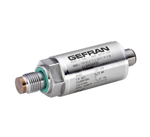
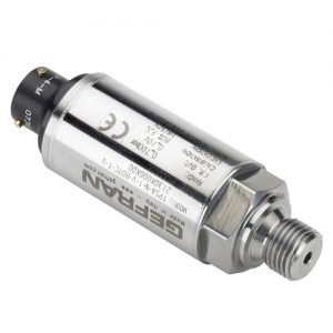
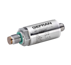
TPFAS Series flush diaphragm pressure transmitters are based on bonded strain gauge on stainless steel technology.
Thanks to the strong flush diaphragm made with 17-4 PH stainless steel, TPFAS is particularly suitable for pressure measurement where the media is with high viscosity (thick fluids, oils, rubber, pulps, chemical products, etc.) and small size diaphragm is required while internal measuring chamber transducers cannot be used.
The high thickness of the diapragm makes the product very reliable and suitable for heavy industrial application.
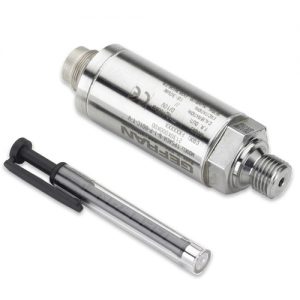
Internal state of the art electronics allows a wide range of cur-
rent and voltage signal outputs, as well as the innovative “Digital Autozero” function is able to perform an easy and quick automatic zero adjustment after the installation, simply with the touch of a magnetic pen or by short circuiting two pins on the electrical connector.
TECHNICAL DATA OF TPFAS
| Output signal | VOLTAGE | CURRENT |
| Accuracy at room temperature (1) | ±0.5% FSO * | |
| Non-Linearity (BFSL) | ±0.25% FSO | |
| Hysteresis | ±0.1% FSO | |
| Repeatability | ±0.05% FSO | |
| Torque effect | <±3% FSO | |
| Measurement range | from 0…25 to 0…600 bar / from 0…350 to 0…9000 psi | |
| Resolution | Infinite | |
| Overpressure (without degrading performance) (2) | 3 x Full Scale | |
| Pressure containment (Burst test (3) | 4 x Full Scale (max 2000 bar) | |
| Pressure media | Fluid compatible with Inox 17-4PH (1.4542) | |
| Body material | Inox AISI 304 | |
| Power supply | B/M/P/R 10…30Vdc C/N/Q 15…30Vdc | 10…30Vdc |
| Supply sensitivity | < 0.0015% FSO/V | |
| Measuring principle | Bonded strain gauge on stainless steel (4 active arms) | |
| Insulation resistance | > 1000 MΩ @ 50Vdc | |
| Zero output signal | B, C, M, N, P, Q, R | 4mA (E) |
| Full scale output signal | B, C, M, N, P, Q, R | 20mA (E) |
| Max current absorption | 13mA | 32mA |
| Max allowed load | 1mA | see diagram |
| Zero adjustment | ±10% FSO magnetic or external (see options) | |
| Calibration signal | 80% FSO nominal (optional) | |
| Long term stability | < 0.2% FSO/Year typical | |
| Operating temperature range (process) (5) | -40…+120°C (-40…+248°F) | |
| Compensated temperature range (4) | -10…+85°C (14…+185°F) | |
| Storage temperature range | -40…+125°C (-40…+257°F) | |
| Temperature effects over compensated range (zero-span) | ±0.01% FSO/°C typical (±0.02% FSO/°C max.) | |
| Response time (10…90%FSO) | < 1 msec. | |
| Start-up time | < 500 msec. | |
| Mounting position effects | Negligible | |
| Humidity | Up to 100%RH non-condensing | |
| Weight | 110 gr. nominal | |
| Mechanical shock | 100g/11msec according to IEC 60068-2-27 | |
| Vibrations | 20g max at 10…2000Hz according to IEC 60068-2-6 | |
| Ingress protection | IP65/IP66/IP67 | |
| Output short circuit and reverse polarity protection | YES | |
FSO = Full Scale Output (output signal at rated pressure)
- Includes combined effects of Non-Linearity BFSL (Best Fit Straight Line), Hysteresis and Repeatability, Zero-offset and Span-offset (acc. to IEC 61298-2)
- tested for more than 1000 strokes with single duration <
- tested for more than 100 strokes with single duration <
- temperature outside compensated range may cause zero signal drift
- ambient and/or electronics part temperature must not exceed 105°C
* Zero offset <±1%FSO on basic version (without Autozero function)




Reviews
There are no reviews yet.