Description
Overview
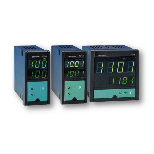
Microprocessor controller, 48×96 (1/8 DIN) format for model 1000 and 96×96 (1/4 DIN) format for models 1001 and 1101 manufactured using SMT.
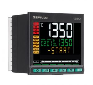
The 1000 family of controllers provide a complete operator interface, with a Lexan membrane faceplate to give IP54 frontal protection that has 3 keys, two green LED displays with 3 (1000) or 4 (1001 and 1101) digits, and red LED indicators for the 3 alarm relay outputs and a green LED for the main control output.
The main input for the control variable is universal and provides the possibility of connecting different types of signal:
- Thermocouples of types J, K, N, S, R, T
- Resistance thermometer Pt100 (3-wire)
- Linear inputs: 0-50mV, 10-50mV keyboard definable 2-10V, 0-10V, 0-20mA, 4-20mA with an external shunt.
An auxiliary analogue input is available for a current transformer input.
The instrument has a double control output that is both relay (5A, 250Vac at cosφ =1) and static (24Vdc, max.20mA) and up to a maximum of 3 alarm relay outputs (3A, 250Vac).
Alternatively, the control output can be analogue (0-20mA, 4-20mA or 0-10V, 2-10V).
The optional communications port can be current loop, or RS485 with GEFRAN (Cencal) protocol with a maximum speed of 9600 baud (RS485).
The programming of the instrument is simplified by the grouping of the parameters into function blocks.
Access to the configuration parameters is protected by a hardware jumper and different values of a protection code can be used to restrict the number of parameters that can be displayed and modified by the user.
TECHNICAL DATA OF 1000-1001-1101
GENERAL
Microprocessor controller, 48×96 (1/8 DIN) format for model 1000 and 96×96 (1/4 DIN) format for models 1001 and 1101 manufactured using SMT.
The 1000 family of controllers provide a complete operator interface, with a Lexan membrane faceplate to give IP54 frontal protection that has 3 keys, two green LED displays with 3 (1000) or 4 (1001 and 1101) digits, and red LED indicators for the 3 alarm relay outputs and a green LED for the main control output.
The main input for the control variable is universal and provides the possibility of connecting different types of signal:
ï Thermocouples of types J, K, N, S, R, T ï Resistance thermometer Pt100 (3-wire) ï Linear inputs:
0-50mV, 10-50mV keyboard definable 2-10V, 0-10V, 0-20mA, 4-20mA with an
external shunt.
An auxiliary analogue input is available for a current transformer input.
The instrument has a double control out- put that is both relay (5A a 250Vac
/30Vdc cosj = 1) and static (24Vdc ± 10%, 12Vmin a 20mA) and up to a maxi- mum of 3 alarm relay outputs (5A, 250Vac/30Vdc cosj = 1).
Alternatively, the control output can be analogue (0-20mA, 4-20mA or 0-10V, 2-10V).
The optional communications port can be Current Loop or RS485 with GEFRAN (Cencal) protocol with a maximum speed of 9600 baud (RS485).
The programming of the instrument is simplified by the grouping of the parame- ters into function blocks.
Access to the configuration parameters is protected by a hardware jumper and a protection code can be used to restrict the number of parameters that can be displayed and modified by the user.
A PC programming kit is available for even simpler configuration, composed of a cable and a guided program for Windows environment (see data sheet code WINSTRUM).
TECHNICAL DATA
INPUTS
Accuracy 0,5% f.s. ± 1 digit Sampling time 120msec
TC- Thermocouple
for 1000 instrument
J (Fe-CuNi) 0…800°C / 32…999°F
K (NiCr-Ni) 0…999°C / 32…999°F
N (NiCr-Si-NiSi) 0…999°C / 32…999°F S (Pt10Rh-Pt) 0…999°C / 32…999°F R (Pt13Rh-Pt) 0…999°C / 32…999°F
T (Cu-CuNi) -100…400°C / -148…752°F
for 1001, 1101 instruments
J (Fe-CuNi) 0…800°C / 32…999°F
K (NiCr-Ni) 0…1300°C / 32…1999°F
N (NiCr-Si-NiSi) 0…1300°C / 32…1999°F S (Pt10Rh-Pt) 0…1600°C / 32…1999°F R (Pt13Rh-Pt) 0…1600°C / 32…1999°F T (Cu-CuNi) -100…400°C / -148…752°F
Configured from the faceplate.
The error on the ambient temperature compensation is 0,05°C for every 1°C variation. Over and under range, erro- neous connection and opencircuit probe messages.
RTD 2/3-wires
for 1000 instrument
Pt100 -19,9…99,9°C / -19,9…99,9°F Pt100 -199…400°C / -199…752°F
RTD 2/3-wires
for 1001, 1101 instruments
Pt100 -199,9…199,9°C / -199,9…199,9°F Pt100 -200…400°C / -328…752°F
DC – Linear
0…50mV, 10…50mV
Ri > 1MW
To be used only with external shunt on the controller for 0…10V, 0…20mA, 4…20mA signals.
OUTPUTS
Main output with direct action (heating) or inverse action (cooling).
Relay
With rating 5A at 250Vac/30Vdc cosj =1 (3,5A at cosj = 0,4);
Spark suppression on the NO contact. (Order code R0);
Logic
24V± 10%, Rout = 470W
(12Vmin a 20mA).
Protected against inverse polarity and shortcircuit.
Continuous
0…20mA or 4…20mA dc output on a max. resistance of 500W configurable as 0…10V with 500W load.
Rload ³ 47KW. (order code V and I)
SERIAL LINE
Optoisolated 4-wires.
Passive Current Loop (1200 baud) inter- face or RS485 4-wires (1200/2400/4800/9600 baud).
Protocol: GEFRAN CENCAL
POWER SUPPLY
Standard: 100…240Vac/dc ± 10% on request: 11…27Vac/dc ± 10%
50/60Hz; 9VA max.
Protection by internal fuse not serviceable by the user.
AMBIENT CONDITIONS
Working temperature: 0…50°C Storage temperature: -20…70°C Humidity: 20…85%Ur non condensing
CONTROL
On/Off, P, PD, PID either for heating or cooling, with parameters configurable from the faceplate:
- Proportional band: 0,0…99,9% s.
- Integral time: 0,0…99,9 min
- Derivative time:
0,0…9,99 min (0,0…19,99 min)
- Reset power (proportional band position): ..100%.
- Hysteresis (only for On/Off control):
-199…999 (-999…1999) digit.
- Cycle time: -2…200 sec (0 for On/Off control).
- Soft-start (gradual increase of main out- put power over a predetermined time on switch on): ..99,9 min
- Manual reset (correction of the offset after setting):
-199…999 (-999…1999) digit.
- Offset (setting a difference between the actual measurement of the input probe and the value read by the controller):
-199…300 (-300…300) digit.
- Automatic/Manual function with bum- pless transfer between manual and auto-
- Automatic power on and power off to disactivate the
ALARMS
- 3 alarms, settable as absolute, deviation or symmetrical deviation alarm with respect to the control setpoint with confi- gurable mode (Hi or Lo).
- The alarm point may be set anywhere within the configured
- AL1 alarm with PD action with configu- rable
- Proportional band is set for the hystere- sis of AL1 in the range:
-199…999 (-999…1999) digit.
- Derivative time:
0,0…9,99 (0,0…19,99)min.
- Cycle time: ..200 sec (0 for On/Off alarm).
- Alarm (AL3) may be used as opencircuit load alarm (HB) when used with input from a current transformer; configurable current scale: ..99,9 (0…199,9)
- LBA (Loop Break Alarm) function
- Intervention time and power output in the alarm condition are configurable from the
- Hysteresis for the alarm setpoint is confi- gurable from the faceplate in the range:
-199…999 (-999…1999) digit.
WEIGHT
320g (1000)
400g (1001, 1101)




Reviews
There are no reviews yet.